
UTV Mirror Visibility Engineering: Information Systems, Sightlines & Information Fidelity
Most discussions about UTV mirrors focus on mirror size, field of view, or mounting style. However, UTV Mirror Visibility Engineering begins with a different question: how does information move from the environment to the driver? A mirror is not simply a reflective surface attached to a roll cage. Instead, it functions as part of a larger information system that helps drivers interpret terrain, obstacles, vehicles, and changing trail conditions while operating at speed. As modern sport UTVs become faster, wider, and more capable, visibility depends on far more than mirror placement alone. Vehicle geometry, sightline obstruction, optic placement, information fidelity, and mirror architecture all influence the quality of information available to the driver.

UTV Mirror Visibility Engineering Starts With Information Systems
Every UTV operates within a visibility environment. The driver receives information from the terrain ahead, the trail behind, nearby vehicles, obstacles, weather conditions, and changing terrain features. However, that information does not travel directly from the environment to the driver. Instead, it passes through a series of physical interfaces that include vehicle geometry, windshield openings, A-pillars, body panels, mirror systems, and driver position. Together, these components form an information system.
Consequently, the primary purpose of a mirror extends beyond simply reflecting an image. A mirror functions as an information transfer device that helps drivers observe and interpret conditions outside their direct field of view. When the information system performs well, drivers can quickly identify terrain changes, approaching vehicles, and potential hazards. Conversely, when visibility becomes restricted through poor optic placement, excessive vibration, structural obstruction, or optical distortion, the quality of information available to the driver begins to degrade.
For a deeper understanding of the mechanical systems that support mirror performance, review our UTV Mirror Engineering Guide. Likewise, our Form Closure vs Force Closure article explains how retention architecture influences long-term stability under vibration, thermal cycling, and dynamic loading.
Why Modern Sport UTVs Create Visibility Challenges
Although every UTV uses mirrors to improve visibility, not every platform creates the same visibility challenges. Modern sport UTVs have evolved toward wider suspension systems, larger tires, reinforced safety structures, and increasingly aggressive bodywork. As a result, drivers often encounter visibility limitations that did not exist on earlier generations of machines.
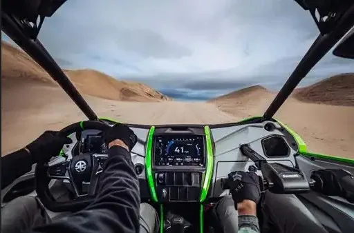
A-pillars represent one of the most significant contributors to sightline obstruction. While manufacturers continue refining chassis design, every vehicle requires structural members to support occupant protection. Consequently, portions of the driver’s forward field of view become occupied by structural elements rather than environmental information. What remains is the driver’s usable viewing corridor.
However, A-pillars are only one piece of the equation. Vehicle width, rear suspension geometry, body flare, seating position, and cage design also influence visibility. For example, the Polaris RZR platform creates different visibility challenges than the Can-Am Maverick X3 or Maverick R. Likewise, utility-focused platforms such as the Polaris Ranger and Can-Am Defender present different sightline considerations than dedicated sport machines.
Therefore, visibility engineering must account for the complete vehicle rather than the mirror alone. The goal is not simply mounting a mirror to a roll cage. Instead, the objective is maximizing the amount of useful environmental information available to the driver while minimizing structural obstruction and unnecessary visual interference.
These principles become easier to understand when examining real-world vehicle platforms. For example, our Polaris RZR Accessories & Side Mirrors guide explores visibility geometry on the RZR platform, while our Can-Am Maverick Accessories guide examines how inward A-pillars and wide rear bodywork influence rearward visibility. Similarly, our Polaris Ranger Side Mirrors for Cab Models and Can-Am Defender Accessories Fitment Guide discuss visibility considerations on utility-focused machines.


Visibility Corridors, Sightline Geometry and Rearward Observation
Modern UTVs create visibility constraints from both the front and rear of the vehicle. While drivers often focus on what can be seen directly through the windshield, visibility is equally influenced by the amount of information available around structural members such as A-pillars, roof supports, body panels, and suspension components.
Engineers often describe this available visual space as a viewing corridor. Rather than evaluating visibility as a single field of view, viewing corridors examine how much useful environmental information remains visible after structural obstructions are considered.
As sport UTVs have evolved, manufacturers have introduced stronger chassis structures, larger suspension components, and wider bodywork. Although these changes improve vehicle performance and occupant protection, they can also reduce the amount of information available to the driver.

Forward visibility represents only one portion of the information system. Although drivers often focus on what lies ahead, rearward visibility introduces a separate set of challenges. Wide rear suspension systems, body flare, and vehicle architecture can occupy a significant portion of the reflected image inside a mirror.
Information Fidelity, Mirror Vibration and the Beehive Effect
Modern visibility systems are evaluated by more than field of view alone. Drivers must also be able to interpret the information presented to them accurately and consistently while the vehicle is moving.
Engineers often refer to this concept as information fidelity. In simple terms, information fidelity describes how accurately a system communicates environmental information to the operator. A wide field of view provides little value if vibration prevents the driver from interpreting what they are seeing.
Off-road environments create a particularly demanding operating condition for optical systems. Washboard roads, rock crawling, whoops, high-speed desert terrain, and repeated suspension impacts introduce continuous vibration into the vehicle structure. Those forces eventually reach any accessory mounted to the chassis, including mirrors.
Consequently, visibility becomes both a geometric problem and a mechanical problem. The driver must not only see the environment, but also receive a stable image that can be interpreted correctly while the vehicle is moving.

One common example is what we refer to as the Beehive Effect. Rather than presenting a stable reflected image, the mirror surface oscillates independently from the housing. The driver can still see movement and general shapes; however, detail, distance judgment, and environmental information become increasingly difficult to interpret.
The result is not necessarily complete loss of visibility. Instead, the quality of the information being delivered to the driver decreases.

As vibration increases, the driver’s ability to distinguish terrain features, obstacles, vehicles, and environmental changes decreases. Therefore, optical stability becomes just as important as field of view when evaluating mirror performance.
That observation leads directly to another engineering question. If vibration can degrade information quality, what causes the optic itself to move independently from the mirror structure?
Floating Glass, Structural Optic Bonding and Optical Stability
Modern mirror systems rely on more than structural retention and visibility geometry. The optic itself must also remain stable if environmental information is to be communicated accurately to the driver.
Earlier, we discussed how vibration can reduce information fidelity through the Beehive Effect. However, vibration reaching the mirror housing does not always affect the optic in the same way. The relationship between the mirror glass and the surrounding structure plays a significant role in determining image stability.
In some mirror designs, the optic is effectively floating within the housing. While the glass remains secured, it is not rigidly coupled to the mass of the mirror body. As vibration enters the assembly, the optic and housing can respond differently to the same input. This difference in movement may amplify image instability and reduce the clarity of the reflected image.
As a result, drivers may continue receiving visual information while simultaneously losing detail, depth cues, and environmental awareness. The mirror still functions, yet the quality of the information reaching the driver decreases.
Engineers often evaluate this behavior as part of the complete optical system rather than the mirror housing alone. Consequently, optical stability becomes just as important as clamp strength, arm rigidity, and retention architecture.
One approach to improving optical stability is Structural Optic Bonding. Rather than allowing the optic to move independently from the mirror housing, the optic is permanently bonded to the surrounding structure so both components behave as a single mechanical assembly.

When vibration enters the system, the optic and housing respond together instead of operating as separate masses. This reduces the opportunity for independent optic movement and helps preserve image stability under dynamic loading.
Although no mirror can eliminate vibration entirely, reducing independent optic movement improves information fidelity and helps maintain a more stable reflected image under real-world operating conditions.
Ultimately, visibility is not simply a question of whether an image exists. The more important question is whether the information contained within that image remains accurate, stable, and usable while the vehicle is moving.
Convex Glass, Fisheye Effect and Field of View
Optical stability determines whether information remains clear while the vehicle is moving. However, another design consideration influences how much information can be presented to the driver in the first place. Mirror curvature directly affects field of view, environmental coverage, and the relationship between object size and perceived distance within the reflected image.
Most UTV mirrors use either flat glass or convex glass. Flat glass produces an image with minimal distortion and accurate scale representation. As a result, objects appear close to their actual size and distance. However, the available field of view remains limited to the physical dimensions of the mirror.
Convex glass introduces curvature into the reflective surface. Because the optic bends reflected light over a wider area, more of the surrounding environment can be displayed within the same mirror housing.

Increasing field of view creates a tradeoff. As curvature increases, reflected objects occupy a smaller portion of the image. Consequently, vehicles, terrain features, and obstacles may appear farther away than they actually are. This phenomenon is commonly referred to as the fisheye effect.
The objective is not simply to maximize field of view. Instead, engineers must balance environmental coverage against image distortion. Excessive curvature can increase visible area while simultaneously reducing the driver’s ability to accurately judge distance, speed, and object size.
Therefore, mirror design becomes an exercise in information management rather than simply increasing reflected area.
In off-road environments, drivers constantly process terrain features, approaching vehicles, suspension movement, dust conditions, and trail obstacles. A mirror that provides additional coverage without introducing excessive distortion can improve environmental awareness while preserving information fidelity.
As a result, mirror curvature must be evaluated alongside visibility geometry, optic stability, vibration control, and structural retention when assessing overall mirror performance.
Load Paths, Function Allocation and Why Mirrors Droop
Every mirror system ultimately becomes a question of load management. While visibility, optics, and information fidelity influence what the driver can see, mechanical architecture determines whether that view remains stable over time. Engineers refer to the route forces travel through a structure as a load path. Understanding these load paths helps explain why some mirrors maintain position while others gradually drift, sag, or require repeated adjustment.
A modern UTV mirror experiences multiple sources of loading simultaneously. Vehicle vibration introduces continuous oscillation. Gravity applies a constant downward force to the mirror assembly. Aerodynamic drag increases with vehicle speed. Additional accessories such as pod lights, communication devices, or action cameras add further mass and leverage.
Each of these forces must travel through the mirror system before reaching the vehicle structure.

Problems often occur when a single component performs multiple functions simultaneously. In many traditional mirror systems, a spherical ball-and-socket joint serves as both the adjustment mechanism and the primary structural retention interface.
Initially, this arrangement may provide acceptable performance. However, the same joint responsible for setting viewing angle must also resist vibration, gravity, aerodynamic drag, impact loading, and accessory weight.
.As vibration cycles accumulate, microscopic wear develops at friction interfaces. Thermal cycling causes repeated expansion and contraction. Adjustment events further disturb the contact surfaces responsible for retention. Consequently, available preload gradually decreases over time.
When holding force decreases while applied loads remain constant, the available safety margin becomes smaller.

Eventually, the adjustment interface begins carrying structural loads it was never intended to manage alone. Once applied torque exceeds available friction, gradual movement begins. Riders often describe this condition as mirror droop.
In reality, droop is rarely caused by a single event. Instead, it is typically the result of load accumulation, preload reduction, and function overlap occurring within the same mechanical interface.
This is why engineers often separate functions within a mechanical system. Structural retention, breakaway protection, accessory mounting, and optical adjustment can each be assigned to dedicated interfaces designed specifically for those tasks. By distributing responsibilities throughout the load path, no single component becomes responsible for managing every force acting on the assembly.
For a deeper look at why some mirror systems experience vibration, drift, and repeated adjustment issues, see our article:
Side-by-Side Mirrors That Actually Work: Why Most UTV Mirrors Fail and What to Use Instead
UTV Mirror Engineering Is About Managing Information
Throughout this article, we have examined visibility corridors, vibration, information fidelity, optical stability, load paths, and retention architecture. Although each concept can be analyzed independently, real-world mirror systems must address all of them simultaneously.
A mirror that provides a wide field of view but vibrates excessively reduces information quality. Likewise, a mirror that remains structurally stable but reflects mostly vehicle bodywork limits environmental awareness. Effective mirror design requires balancing optical, structural, and mechanical considerations into a single system.
Engineers often evaluate mirror performance using individual metrics such as field of view, clamp strength, vibration resistance, or adjustment range. However, drivers do not experience these characteristics independently. Instead, they experience the quality of information reaching them while operating the vehicle.
For this reason, modern mirror systems can be viewed as information systems rather than simple reflective surfaces.
Every design decision influences the quality of information available to the driver. A-pillar placement affects visibility corridors. Mirror placement affects environmental coverage. Glass curvature influences field of view and distance perception. Structural retention affects stability. Optical bonding influences image clarity during vibration. Load path management determines whether the mirror maintains its intended position over time.
Each element contributes to the driver’s ability to interpret terrain, obstacles, vehicles, and environmental conditions accurately.
As modern sport UTV platforms continue evolving, visibility challenges continue evolving as well. Larger suspension systems, wider bodywork, increased vehicle speeds, and more complex accessory integration place greater demands on mirror systems than ever before.
Consequently, mirror engineering has become increasingly focused on managing information, preserving image quality, and maintaining stability under demanding operating conditions.
Whether evaluating a Polaris RZR, Can-Am Maverick, Kawasaki KRX, Yamaha Wolverine RMAX, Polaris Ranger, Can-Am Defender, or Polaris Xpedition, the same engineering principles remain applicable. Visibility corridors, information fidelity, load paths, and structural retention continue to determine how effectively environmental information reaches the driver.
Understanding these concepts helps riders make more informed decisions when selecting mirrors and accessories for their machine.
Engineering Disclaimer
The information presented in this article is intended for educational and informational purposes only. It discusses general engineering principles related to visibility systems, vibration, optics, load paths, retention architecture, and mirror performance in off-road environments.
Examples and illustrations are provided to explain mechanical concepts and should not be interpreted as evaluations of any specific manufacturer, product, or competitor unless expressly identified.
Vehicle geometry, installation quality, operating conditions, maintenance practices, accessory configuration, and rider behavior can all influence real-world performance. Consequently, results may vary between vehicles and applications.
This article is not a legal opinion, patent opinion, engineering certification, or safety recommendation. Readers should independently evaluate products and consult qualified professionals when making vehicle modification, installation, or safety-related decisions.
UTV Mirror Engineering FAQ
Mirror droop typically occurs when the same interface is responsible for both adjustment and structural retention. As vibration, thermal cycling, wear, and repeated adjustment reduce available preload, the holding force available at the adjustment interface decreases. Once applied torque exceeds available retention force, gradual movement can occur.
Mirror vibration is influenced by multiple factors including mounting rigidity, arm length, mirror mass, optic retention, and vehicle vibration characteristics. Systems that allow independent optic movement can experience reduced image stability even when the mirror housing itself remains secure.
The Beehive Effect describes a condition where the optic oscillates independently from the mirror housing. Although the driver can still see general shapes and movement, image detail becomes more difficult to interpret because the reflected image is no longer stable.
Not necessarily. Visibility depends on both field of view and information quality. A larger mirror may provide additional coverage, but mirror placement, optic stability, bodywork obstruction, and glass curvature all influence how much useful environmental information reaches the driver.
Flat glass maintains object size and distance with minimal distortion but provides a narrower field of view. Convex glass increases environmental coverage by reflecting a wider area; however, objects appear smaller and farther away as curvature increases.
Modern sport UTVs often use wider suspension systems, larger body panels, stronger A-pillars, and increased occupant protection structures. While these features improve performance and safety, they can reduce the amount of environmental information visible around the vehicle.
A load path describes how forces travel through a mechanical assembly. Gravity, vibration, aerodynamic drag, impact loads, and accessory weight all move through the mirror structure before reaching the vehicle. Understanding load paths helps explain why some mirror systems remain stable while others require repeated adjustment.
Mirror placement determines how much of the reflected image is dedicated to the surrounding environment versus the vehicle itself. Proper optic placement can increase usable environmental information without increasing mirror size.

Comments are closed